METHOD STATEMENT FOR EARTHING, BONDING AND LIGHTNING

Method Statement For Earthing, Bonding & Lightning
1.Purpose
The purpose of this MST is to define the required resources and procedures that shall guide the installation of earthing, bonding, and lightning protection systems so that all activities to be carried out shall be in compliance with construction procedures and requirements.
2. Scope of Works
The scope of this methodology covers, but not limited to, lightning protection, Grounding, Bonding, Testing and Termination in accordance with approved shop drawings, applicable codes and other project technical documents.
3.Objectives
The objective is to:
- To execute the work in the best quality and to achieve the intent of design.
- To ensure maximum safety is established during activity.
- To ensure that works are done in compliance with all Cleint requirements.
- To establish coordination between all trades accordingly during execution.
4. List of Acronyms
- QMS Quality Management System
- QA/QC Quality Assurance / Quality Control
- MST Method Statement
- ITP Inspection and Test Plan
- CL Checklist
- QMP: Quality Management Plan
- OHSP Occupational Health and Safety Plan
- EMS Environmental Management System
5. Reference Documents and Standards
- Project Contract Document
- Approved Shop Drawing
- Approved Materials Submittal
- Approved ITP
- Saudi Building Code
- Saudi Electric Company
- Client Construction Procedure
6. Responsibilities
6.1 Project Manager
- The Project Manager is the overall responsible for all project He shall ensure that all activities are time-bound, quality-bound, and safety-bound and are in line with the contract requirements.
6.2 QA/QC Manager
- The QA/QC Manager shall oversee the project with respect to all quality, Ensuring the consistency of quality compliance, products and services with reference to all applicable codes and standards.
6.3 Construction Manager
- The Construction Manager shall be responsible for implementation of this method statement & oversee all construction work activities as required in the approved technical documents.
- He shall ensure that all permits and coordination have been done prior to initiating the work.
- He shall ensure that all works are done as per approved drawings, materials and qualified Personnel.
6.4 QA/QC Engineer
- He shall be responsible for performing inspections/checking of materials, workmanship, required documentation, evaluation and witnessing field-related tests on-site and off-site as per approved drawing and project requirements.
- He shall be responsible for determining non-conformances and ensuring it’s closed on time and properly.
- He shall conduct all required inspections and tests as specified in the approved ITP.
6.5 Site Engineer
- He shall be responsible for supervision activities and implementation of this method statement, approved shop drawing and other technical requirements, including the quality aspects of materials and good workmanship.
6.6 HSE Officer
- He shall ensure that all activities are in full compliance with the project HSE requirements.
He shall carryout all duties and responsibilities with respect to the approved OHS plan.
6.7 Surveyor
- He shall be responsible for all survey related works such as lines, elevations and all setting-out, leveling, and other survey works.
7. Health, Safety and Environment Measures
7.1 General Safety Precautions
- Monitor and ensure that all safety precautions are being followed by the respective engineers, supervisory staff,
- Ensure that the supervisory staff have checked that all personnel have undergone any necessary induction trainings and that all personnel are equipped with (PPE) Personal Protective Equipment.
- Ensure that all works have undergone the necessary pre-commencement STARRT talk provided by the works supervisor.
- Periodically inspect all works ensuring adequate signage and permits are in place.
- Conduct inspections as and where necessary to ensure plant equipment is in full compliance with the projects requirements.
- Where deemed appropriate issue corrective action notices and or observation reports in line with procedures.
7.2 Fire Control / Contingency Plan
- As per approved Safety Emergency Response Plan
7.3 Emergency Procedure
- As per approved Safety Emergency Response Plan
7.4 Accident Reporting Contact
- As per approved Safety Emergency Response Plan
8. Quality Control During Activities
- All works shall be inspected according to the approved ITP.
- Checklist shall be used during inspection to maintain quality consistency.
- All activities shall be carried out in proper coordination with other trades.
- Good workmanship shall be adapted at all time.
- All works must comply with the relevant and applicable standards.
9. Control of Overlapping Activities and Work Interface with other contractors
- In any case if there is an overlapping of works with other contractor or subcontractor’s activities, an immediate coordination shall be initiated between the contractors concerned or involved in the area of the activates.
- Work interface areas for each of the contractors shall be highlighted in the concerned drawing and shall be identified or marked at site for exact location and easy references.
- In case of major overlapping dispute which cannot be solved between the contractors or subcontractors, the issue shall be officially communicated to the client /consultant for final resolution.
10. List of Equipment and Tools
- Portable Drilling Rig as per Site Requirements/Conditions.
- Portable Tool Box ( Weld handle clamps, flint gun, mould, brush etc ).
- Crimping Tools.
- Drilling, Grinding and Filling Machines.
- Earth Resistance Tester / Megger Tester (Calibration Certificate shall be provided prior to testing).
- Equipotential Bar/ Earth Bar.
- Scaffold (Fixed, Mobile).
- Cable Cutter.
- Wrench and Die set.
- Hand Tools.
11. Materials
All Materials to be installed during the work shall be as per approved materials submittals.
12. Materials Delivery, Handling and Storage
12.1 Material Delivery
-
- All materials shall be delivered to the site using the appropriate channel /route.
- Materials shall be properly secured on the transportation means to avoid any accident.
- The materials temporary /final storage locations must be cleared and made ready prior to delivery.
12.2 Material Handling
- All heavy materials lifting procedures shall be planned before offloading.
- In case where heavy materials shall be raised, the appropriate equipment shall be used to offload.
- In case of critical lifting, a lifting plan shall be provided with its risk assessment accordingly.
12.3 Material Storage
- All permanent storage areas shall be prepared accordingly prior to any storage.
- All temporary storage areas shall be prepared accordingly prior to any storage.
- Materials shall be stored and properly secured against damages.
- Materials shall be stored as per manufacturer’s recommendation where necessary.
12.4 Material Inspection
- All materials to be installed shall be inspected and tested as per approved ITP prior to proceeding to install.
- All materials delivered at site which are defective or nonconforming with the materials approved submittals shall be quickly quarantined or taken out of site to prevent its usage.
- Materials delivered to site with minor deformities shall be fixed at In a case it cannot be fixed at site, then a coordination will be initiated with supplier to solve the issue.
13. Pre-Installation Activities
- Ensure that the shop drawings and other documents are approved and available prior to starting the activities.
- A survey marking shall be done where required prior to installation for accuracy.
- Investigate the areas of installation and ensure there are no obstructions.
- Establish site coordination with all trades to ensure no clashes of services.
- Ensure all required safety permits have been obtained accordingly.
- Conduct a workshop with the workers if required prior to starting the work.
- Ensure that all certificates if required are available accordingly.
- Prior to boring the soil, ensure there are no existing underground facility is located on the spot
- Ensure that all devices to be used for measurements are calibrated and up to date.
- Check the earthing cable routing locations in co-ordination with other services and ensure there are no obstruction to each other or clashing.
- Ensure easy access and sufficient clearance for servicing and maintenance e. for replacement of cable etc.
14. Work Methodology
14.1 Boring for Earth Pit, Soil Resistivity Test and Installation of Earth Rod
Prior to boring the soil, exact location shall be taken from the approved drawing. In absence of clarity of exact location, a survey shall be conducted to determine exact location of the hole as per approved drawing.
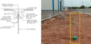
- Verify underground facilities and ensure that drilling point is free from any underground utility like cable, pipeline etc.
- Location of drilling to be marked up by surveyor as per latest approved
- After determining the exact location for the pit, mark the ground and set-up the boring machine.
- Ensure that the machine its aligned with the mark and vertically correct before proceeding to drill the hole.
- While drilling, avoid soil from collapsing during boring.
- Samples of the soil extracted from the ground shall be monitored to determine when depth reaches the required level (Refer to Geotechnical Study Report attached). Take a measurement of the current depth.
- After determining the current depth from the ground level, set-up the earth rod hammer machine to drive the earth rod inside the hole.
- After setting up the hammer machine, proceed to drive the earth rod inside the pit until you achieve the required depth of summer water level point.
- After installing the earth rod to required depth, ground resistivity test shall be done to ensure compliance to required ohm.
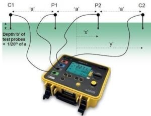
- After achieving the required resistance value, backfill the hole accordingly to ensure proper ground levelling is achieved.
- Finally, install the concrete inspection pit in accordance with the installation drawing and ensuring that orientation, finish floor level and finishing is (Ensure that “electrical earth” is engraved on the concrete cover – as required).

- After completing the installation, work area shall be tidied without any remains of consumable. All wastes and excess materials associated with the activity shall be disposed accordingly.
14.2 Installation of Earth Cable, Bare Copper Bars and Testing
- Earth cables shall run through Trays, Trunks, Conduits, Ducts or direct buried as required.
- Installation of earth cables and bare copper bars shall be as per approved shop
- Observe spacing as required and fix cable ties at required intervals as appropriate to avoid drawings.
- Terminate all the cables and bars using appropriate accessories accordingly.
- Connect earth cables to Electrical Panels, Motor, Switches, Sockets, Trunking, Trays, Structure, etc. via dedicated bus bars as per standard installation practice and approved shop drawings.
- Install earth bars and connect earth cable to the bus bar fed from the earth
- Apply anti corrosion grease to the connection points if necessary.

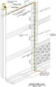
- Prior to termination, all Earth cables shall undergo the continuity test using a multi (Confirm that the devices calibration certificate is still valid).
- Take record of all values from the test result and verify if accepted with reference to specification requirement.
- After the cable testing and termination on the earth bar and to the other end of the equipment terminal point, fix the cables in a proper dressed manner using cable ties.
- Use a torque wrench to tighten the terminal nuts by setting the torque point (N/m) to the manufacturer’s recommended values.
- After torque point is completed, mark the terminal nut /bolt for reference purposes.

14.3 Installation of Earth Bar
- The earth bar shall be installed according to the approved shop drawing and manufacturer’s
- After confirming the location and height of installation, place the bar on the wall (check alignment) and mark the bolting parts to the wall.
- Drill the marked points on the wall using the correct size of drill bit as per the required installation Afterwards, install the base accessories and bolt the earth bar to the wall accordingly.
- After completing the installation, work area shall be tidied without any remains of consumable. All wastes and excess materials associated with the activity shall be disposed accordingly.

14.4 Installation of Earth Bonding Materials (Earth Strap)
- Install earth strap at required fittings joining two parts of the race way to ensure proper continuity of the containment.
- At the fitting joint segment, insert the bolt from the internal part and ensure enough length to the outer part.
- At the outer part of the bolt, fix both end of strap and fasten it with a nut to ensure proper tightness.


14.5 Installation of Earth Cable Gland, Lugs and Accessories
- All cables passing through an opening or running through a flexible or rigid I conduit shall be glanded to avoid damages. Also, prior to termination, all cable requiring lugs and crimping shall be considered as well.
- Cable gland installation shall be done appropriately.

- For cable lugs installation, after selecting the correct lug as per diameter of the cable; fit the lug end to the exposed strand and crimp.
- After crimping, apply insulation to the lug if applicable and apply a light heat to ensure the insulation laps with the lug head properly.


14.6 Labelling and Tagging of the Earth Cables Accordingly
- All Earth Cables shall be tagged or labelled

15. As-built Drawings
15.1Redline / Hand sketch drawings
- During activity, all modification done at site due to site conditions which are not consistent with the approved shop drawing shall be recorded accordingly.
- After final inspection of the activity or installation, the drawing shall be issued to the technical team to proceed As-built compilation.
16. Final As-built drawings
- All As-built drawings shall be submitted accordingly once testing and commissioning works are completed and approved by the client.


