Method Statement For Installation of Horizontal Life line and Working on Roof

Method Statement For Installation of Horizontal Life line and Working on Roof
1.Purpose:-
Provide guidance to users on the need for proper installation of fall protection to either remove the fall hazard, prevent access to the fall hazard, restrict worker movement at the fall hazard, or provide the proper fall arrest equipment; Illustrate fall protection systems; Familiarize fall protection equipment users with the appropriate standards pertaining to their use. Assist in the proper selection, care, use and inspection of fall protection equipment.
2.Scope:-
This SOP covers, all areas (permanent or temporary) where working at height is necessary under Contractor.
3.Procedure:-
3.1 Components of a Personal Fall Arrest System (Horizontal Life-Line):-
There are three vital components that make up a complete fall protection system.
These are the ABC’s of fall protection
A. Anchorage
B .Body support
C. Means of Connection
- There are three vital components that make upa complete fall protection system.
- These are the ABCs of fall protection:
Anchorage.
Body support. Means of Connection. Each must be in place and properly used to provide maximum worker protection. While each of component vital to worker safety, the connecting device is the critical link in assembling a safe fall protectionsystem since it bears the greatest force during a fall.
Careful consideration must be given to the selection, materials, construction and inspection/maintenance of fall Protection equipment before, during and after a connecting device has been selected. An anchorage, as defined, is a secure point ofattachment for lifelines, lanyards or
3.1.1- Without a full harness working above 1.8 meters, no helmet, safety shoes, vest, hand gloves, or safety glasses are not allowed to work.
3.1.2- Appropriate safety methods will be determined for minimize risks in selected For this particular works, an engineered HLL will be installedand used.
3.1.3- Snap hook/Pelican hook shall be hooked of directly to the steel cable.
3.1.4- Trainings about working at height must be given to all staff, along with orientation and planned trainings. All employees must be raised aware of work that will be done and safety measures that must be taken.
3.1.5- Persons who have a fear of height, fatigue, attention loss, or the same kind of disease are not allowed to work.
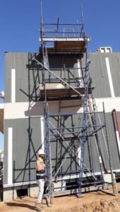
3.2- Installation Procedure of Tubular Steel Frame “A Type” for Horizontal LifeLine:-
3.2.1- Installation and dismantling of tubular steel frame “A type” must be done by experienced staff under the authorized person’s control and must be consider measures and material properties. Proper PPE’S must be worn during the installation and dismantling
3.2.2- A work permit must be obtained and reviewed with workers involved with the work. A review of the permit shall be documented in the PTB.
3.2.3- Scaffolding towers shall be erected and used for access and egress. A certified scaffolder shall inspect the scaffolding tower prior to use and tagged with a green tag prior to use.
3.2.4- When A‐frame can be placed on the ground, the ground condition must be suitable for them. After installation, A‐frame must be fixed firmly to the ground. A‐ frame will be strengthened by using of metal profiles, under thecontrol of a certified scaffold supervisor/inspector.
3.2.5- In areas where the A‐ frame will land on top of the metal stairwell decking/steps, welding of the A‐ frame leg to the stairwell landing/steps shall be performed. A‐ frame system/HLL will not be used until inspected by 3rd party.
3.2.6- When working in case any was needed material from below, material that can be moved with ropes (with the decision of the certified scaffold supervisor/inspector); one end of the rope is connected to a solid point and staff that is on the scaffold must be directed until material moved from bottom to top.
3.2.7- Concrete blocks or the structure of the portable cabin (I-beam located and decking of the portable cabin) shall be used to secure the steel cable (HLL) to support the life line. The steel cable used for the HLL shall be secured with “bull dog clips”
3.2.8- Set of the concrete blocks with 2 sides of the structure (portable cabin). Concrete blocks are connected and supported properly to wire rope for lifeline.
3.2.9- Meter and more than height, a safety harness must be used, and a lanyard must be tied to safety on the structure for safety. Safety belts will not be removed never except relocation.
3.2.10- Anyone can stop the work in any type of bad weather or any unsafe condition. A‐ frame must be installed and fix to the building structure.
3.2.11- If needed, the A‐frame must be installed to support the structural with outriggers and take the supports from the blocks listed in the building.
3.2.12-Nobody can use a lifeline without third party inspection.

Barricade the area and install a safety sign to warn the employees. NO other workers are allowed on the roof if not involved with roof panel works.
3.2.13- If there is a failure or excessive sway on the A ‐ frame or scaffold tower, the work will be stopped immediately, and issues highlighted will be corrected and re-inspected by the certified scaffolder.
3.2.14- On the scaffolding, all workers must respect their work and be disciplined.
3.2.15- Never smoke when working at height.
Scaffolding For Access
3.3 Using access ladder in the scaffolding tower:-
3.3.1: Ladders must be used only in low‐risk operation in cases where the approval of scaffold supervisor, construction supervisor and site HSE.
3.3.2: Step and connection points will not be looseness.
3.3.3: Ladders will be placed safety during use. Portable ladders, steps in a horizontal position to be smooth, robust, appropriate size, will focus onthe hard shoes.
3.3.4: During the use of portable ladders, ladder skidding will be prevented bytaking necessary measures. Before use folding ladder the moving parts must be fixed firmly
3.3.5: Ladders should always be secured by tying off. The correct angle for positioning a working ladder
3.4 Use of MEWP:-
- MEWP can be used but under NO circumstances are workers allowed to leave thebasket of the MEWP.
- All workers operating the MEWP shall be certified and trained to operate the
- Other workers in the basket, NOT operating the MEWP shall be Well
- MEWP shall NEVER be operated from the ground unless for emergency purposes.Regular use/operation of the MEWP shall be done within the confines of the MEWP basket.
- NO workers are allowed beneath the MEWP basket. The area shall be cordoned
- NO equipment of vehicles are allowed to pass under the boom of the MEWP or basket.Work shall STOP and boom relocated so equipment/vehicles can pass OR traffic re‐routed to avoid driving under booms or baskets.
- MEWP shall not be operated near power lines. operator shall be fully aware ofoverhead structures that may strike the workers head when operating.
- ALL workers shall be using certified (EU, ANSI, CSA, and AUS) recognized safety consensus PFAS gear. All lanyard shall have a shock absorbing All PFAS gear shall beinspected and quarterly color marked.
- Man lift should be inspected from third
- All workers use full body harness during work at height
3.5 Installation of Wire Rope (Anchorage) For Horizontal Life Line:-
A manlift shall be used to install steel cable from one A-frame to the next A-frame. NO workers will be allowed on the roof unless a positive means of connection of the lanyard is secured, OR workers are using manlifts.
As a general rule, it is recommended that a fall arrest system be used anytime when working at an elevated level and exposed to a fall hazard.Trigger heights (for example, 4 feet for general industry workplaces, and6 feet for construction) are dictated by specific standards for the applicable industry. The following is recommended:
Anchorage Steel Rope – Shall be designed, installed and used under the supervision of a qualified person (such as part of a complete personal fall arrest system which maintain safety factor of at least two anchorage Connector, Anchor Sling-I

beam trolley, or other anchorage connector. Body Support ‐ Full bodyharness. Connecting Means ‐ Energy‐absorbing lanyard and fall
Anchorage 16mm steel rope / cable must be properly installed to the A‐type frame from both side of the structures with three pieces of steel rope grip andturn eye buckles
An eye turnbuckle, must be install tofor s for adjusting the tension or length of ropes, cables, tie rods, and other tensioning systems of the life line. It normally consists of two threaded eye bolts, one screwed into

. Each end of a small metal frame, one with aleft‐hand thread and the other with a right‐ hand thread.
Three pieces of Wire Rope Grips must be properly installed randomly to the wire, wire rope grips afford a simple mechanical means of securingthe end of a wire rope. They are appropriate for temporarily securing the end of a wire rope that may need to be shortened from the gripped end.
Analysis & Calculation for Horizontal System:-
Design Parameters = 2 Workers at a time, in spam of 12pm
Safe Working Load (SWR, 16mm) = 36.44 kn
Distance between anchor Points = 12.00 m
Anchor point (concrete Block Set) = 24.18 kn x 2 = 48.96 kn
Engineering Calculations for Horizontal Lifeline fall arreat System:-
- Normal size diameter = d = 16mm
- Net cross section area = A = 100.6 mm2
- distance between anchor length = S = 12m = 1200 mm
- Weight of cable per unit Length = W = 0.01047 kg/cm
- Modulus of Elasticity of cable = E = 140000 kg/cm = 141.215 GPa
- Minimum breaking load = F8 = 182.2 kn
- Sag of cable its own weigth = F1 = 30.00 cm = 0.3 m
- Tengential cable tension at midspan under its own weight = t1 = w x s / 8 x t1 kg
=0.01047 x 1440000/8 x 30
T = 15076 / 240 = 62.41 kg/cm
Calculation for Life Line Installation:-
Cable tension at either enchorage
Under cable weight (Concrete block ste ) = T1 = 61.591 kg
Cable length under its own weight = L1 = S x 1 8 x f1 / 3 x cm
= 12000 x 1.001667
L1 = 1202.00 cm or 12020
A type frame Design Calculations Capacity of A type Frame Tube in Bending:-
M1 = FY x Z
FY = Minumum Yield Stress = 235.00 N/mm sq for En39 / BS 1139 – 5.08mm tube
Z = Plastic Section Modulus = (OD3 – ID3) for 48.3mm OD with wall thickness 5.08mm
= 7871.29 mm3
Therefore Moment = M1 = 235.00 x 787.29
= M1 = 1849753.93 kNm
Design Check: Connection of Short tube Supporting A type frame on I-Beam
Total Axial load acting on both short tube = 36.97 kN
Each short tube is connected with one pair of girder couples SWL for pair of Girder coupler in Distortion = 60.00 kN
60.00 Kn 36.97 kn Therefore, Short Tube is Safe
Design Check: Short tube supporting wire
P=Reaction Due to cable force = 36.97 KN
Maximum bending moment on short tube = P x A x B = 36.97 x 0.03 x .037 = 1.63 kNm
L = 0.0=4m
Installation of roof capping:-
- Use self-threading screws to install the Make sure the screws are inserted into the steel beams onthe roof.
- Only two persons will be allowed to use the man lift bucket, man lift operator with one worker.
- Operator will operate from the
- Cladding will be bought from store area by using boom truck
- Cladding will be shifted on the top of the roof by using
- During the lifting process the area will be properly barricaded and signage’s will be placed
- During the shifting of the material tag line will be used to handle the
- Contractor should identify the location of the capping to be placed as per the approved shop drawing.
Program
- Clearance from all Civil & Electrical from any
- Setting out alignment & levels, marking of
- Leveling as required to check
- Waste disposal if
4.Responsibilities:-
4.1 Project Manager
TAMIMI Project Manager has the overall authority and responsibility for allaspects of the Project. His responsibilities include as:
- Ensuring adherence with the Contractor Company
- Managing site project activities on behalf of the
- Establishing project requirements, policies, organization and
- Monitoring project’s progress and quality, approving final resolution ofall items of non-conformance.
- Approving all
- Ensuring implementation of the Main Contractor QA/QC
- Issuing all project
- Managing project’s
- Initiating and negotiating with Clint for all change orders and work requests and signing change order and / or work requests.
- Preparing, approving and submitting progress reports to the
- Having final authority on all site project activities
4.2 Construction Manager
The Construction Manager controls and coordinates all work activitiescarried out in the construction site. His responsibilities as:
- Establishment and implementation of work procedures in the MS forthe execution of work
- Review detailed construction schedule, including redefinition of priorities where necessary
- Control and coordination of the work entrusted to subcontractors
- Planning and scheduling of the work force and equipment
- Review of the materials delivery schedule
- Preparation of data required for compilation of the Work Progress Report
- Preparation of the change order proposals
4.3 Site Engineers
- The assigned engineer shall ensure that the current drawings relatingto the excavation activity are approved for construction.
- The engineer shall ensure that there are no conflicts with existing services or other discipline issues.
- Co-ordinate all the site activities required for the execution of Work according to the contract.
- Liaise with site representatives of Client and Engineer to coordinate safety.
- Co-ordinate and explain the work to be carried out to the supervisors / Site foreman.
- Ensure the compliance of works with the related approved Quality Control Plan
4.4 QA/Qc Manager
- Representing the project for all quality
- Developing and maintaining the Project Quality
- Verifying implementation and adherence with QA/QC.
- Quality Procedures and / or work
- Preparation of new procedures and / or work
- Reporting items of non-conformance to the Project
- Reporting on the corrective action / resolution of non-
- Verifies program implementation by conducting project specific
- Liaison with NEOM / AECOM to coordinate and assist in NEOMaudits, surveillance, inspections and approvals.
- Establishing, maintaining and overseeing the document control andrecord keeping function.
- Establishing, maintaining, and overseeing the Non-destructive Testing and Wild Engineering functions.
- Quality Monthly Report
- Evaluation of Suppliers and Sub-Contractor’s Quality
- Coordination and supervision of activities related to the collation of the “Project Record Books”
- Preparation and submission of “Two Week Look Ahead Schedule”
- Preparation and submission of “Monthly Management Review Reports” on monthly basis.
- Organize Inspection and Test Plan for procurement, construction and commissioning phases.
4.5 QC Inspector:
- Duties and responsibilities of QA/QC Inspector could be typically enumerated as follows:
- Ensure compliance with the requirements of the contract scope ofwork, technical specifications and contract quality plan.
- Conduct quality control inspection tasks in accordance with the requirements of the established inspection plans.
- Initiate RFI after verification of activities to be offered for
- Signs and dates inspection reports for those inspection steps actually performed. Provides final acceptance sign-off of all prescribed inspection reports attesting to the completeness of the project.
- Calibration and use of the necessary measuring and
- Coordinate for the third-party agency for the required
- Initiate preparation of the job site quality control
- Reporting both verbally and in writing any non-conformance discovered.
- Reporting daily a descriptive of each day’s
- Conduct weekly QA/QC Toolbox
- Shall report/coordinate with Clint personnel for witnessing all inspections and acceptance of the work items.
4.6 Safety Manager
- Ensuring work is carried out in a safe manner and, in an accordance with any manufacturers’ instructions etc., good standards ofworkmanship;
- Ensure site staffs are working in accordance with agreed Risk Assessment and Method Statements (RAMS) particularly where activities have the potential to cause environmental harm;
- Give healthy and safety advise to compete the site wastemanagement plan and, ensure it is followed;
- Ensure that the CEMP is implemented throughout all phases of the project;
- Carry out daily checks on site to ensure the site is secure and tidy;
- Weekly checks and “toolbox talks” carried and Weekly site inspection;
- Reviewing and improving conditions or methods/procedures where appropriate; and,
- Keeping records of and, reporting any incidents and close calls (near misses).
4.7 Environment Manager
The Environmental Manager is responsible for:
- Provide advice to Project Director / Manager / QHSE Manager on measures required to comply with the requirements of applicable environmental legislation and environmental authorities, including the specific requirements of the project approvals and supporting documentation;
- Develop, review, implement and, update this CEMP in accordance tothe requirements of NEOM CEMP;
- Monitor and, report on the implementation of this CEMP and environmental performance;
- Set, monitor and, review environmental objectives and targets;
- Identify areas requiring improvement and, develop action plans, communicate compliance requirements, and, ensure all environmental obligations, including legislative requirements and, approvals are complied with;
- Set, monitor and review environmental objectives and targets;
- Conduct environmental site inspections, auditing, monitoring and training, identify improvement actions and, track implementation of those actions.
- Ensure relevant statutory legislation is monitored and, the requirements followed;
- Maintain adequate environmental records;
- Liaise with stakeholders as required;
- Ensure environmental issues are considered by all staff and are applied to their work;
- Identify, investigate and, report on actual and potential environmental incidents and, non- conformances;
- Develop and, implement corrective and, preventive actions to prevent recurrence of incidents and, non-conformances;
- Attend HSE committee meetings as required; and,
- Monitor the implementation and effectiveness of the
4.8 Safety Officer
- Responsible for the Client’s HSE
- Liaise with Site Engineers in implementation of site Safety Plan and issue safety directives accordingly.
- Makes sure HSE roles, responsibilities, policies, plans and objectives are communicated to all relevant personnel.
- Ensure that PTW requirements has been secured and must beavailable at site
- Liaise with the Project Safety Manager in identify the HSE training requirements of personnel and assist in arranging internal and external
- Investigate accidents and incidents that result in “Lost Time Accidents” (LTA’s).
4.9 Surveyor
The surveyor, under the direction of the nominated chief surveyor, has the responsibility to check the established main reference and check levels at regular intervals.
4.10 Supervisors /Foreman
Supervisors have the direct overall responsibility for the supervision of their allocated area including the direct supervision of the fixers and labors involved and the strict implementation of safety rules and procedures.
5. Compliance to Safety & Protection:-
Prior to starting any work activities, the following major steps would be carefully followed: obtaining the necessary approval and work permit received from permit issuer.
- Main Contrctor shall barricade along with other protective measures required for the
safety of personnel and the premises.
- Only workers and supervisors whose presence is necessary shall be present
6. Quality Control:-
- All Inspections and testing shall be performed as per standards and witnessed by the
- RFI’s will be submitted on time with one day before
7. Test & Quality Records:-
All the test and records shall document the compliance to the project quality plan and other project requirements as per International/Clint and to submit to client at the close of the project and as built to be provided