METHOD STATEMENT OF INSTALLATION AND TESTING OF DUCTING.
1. Scope of Work:
The scope of this method statement is to describe the measures and ways of ductwork with required accessories as per project specification & design.
2. Field of Application:
This method statement which is for the installation of PIR Pre-Insulated Ducts and accessories would be used to make sure the proper way of installing the ducts in the areas where it is designed to be placed such as wall openings, roof, hanging from the ceiling, etc.
3. Purpose:
The purpose of this method statement is to define the specific tasks to be performed at the site ensuring the quality and proper installation of the delivered material.
4. Reference:
-
- HVAC layout design CAD drawing submitted by the client or the contracting company.
- The AutoCAD HVAC design should be the approved drawing from all necessary parties.
- Dimensions are to be strictly followed on the drawings provided unless requested otherwise,
- Material approval documents.
- Purchase Order mentioning the quantity and volume of the Project.
5. Materials:
-
- PIR Pre-Insulated Panels
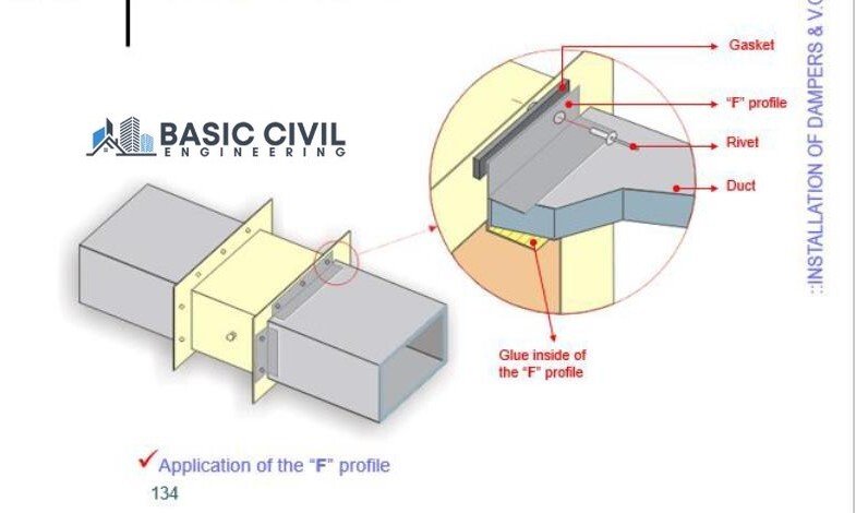
- Aluminum Flanges (Invisible Flange, F Flange, Y Flange, U T Flange)
- PIR Pre-Insulated compatible HVAC grade glue
- PIR Pre-Insulated compatible HVAC grade silicon sealant
- PIR Pre-Insulated compatible HVAC grade Aluminum Tape
- GI-Angle
- H-Bayonet PVC
- PVC Corners
6. Manpower:
-
- Project Manager
- Construction Manager
- Assistant Construction Manager
- Project Engineer
- Site Engineer
- Foreman
- Fabricators/Workers
7. Equipment & Tools:
-
- C Channel
- Threaded rod (diameter to be approved by the Project Engineer on site)
- Nut & washer (diameter to be approved by the Project Engineer on site)
- Ceiling Fischer
- Scaffolding or ladder (if not too much height)
- Mobile scaffolding
- Standard toolkit for duct installation
- Smoke pallet (for Testing of the duct)
- Blower Fan (As per required of the site)
- Portable grinding machine
- Cutter machine
- Hand drill machine
- Hilti drill machine
- Safety helmet
- Safety shoes
- Star screws
- Basic PPE for eye protection from dust, chemical mask, hearing protection, overall body protection
8. Pre-Requisites during Unloading:
-
- During unloading, check all the ducts according to the drawing.
- Separate each machine ducts from each other, based on the markings and the tagged drawings.
- Separate the supply and return lines of each machine.
- Locate and arrange the branch lines of supply and return line.
- Locate and arrange the shoe, elbow and end cap pieces of each line.
- Clear the site for material receival and imstallation.
- Prioritize which machine is to be installed first and schedule the rest accordingly.
9. General Installation Procedure:
- Understand the duct layout and prepare a rough marking of the complete supply and return lines to comprehend hanging positions.
- Use an appropriately sized drill to mark the location of hangers.
- Choose correct size of anchor bolts as per the design and the approval of site engineer.
- Choose the correct size of threaded rod as per the design and the approval of site engineer.
- Install ceiling Fischer and hang the threaded rod on both the sides of the duct.
- Meanwhile, if possible and there’s enough space on the floor, put the complete HVAC layout right below the marked area.
- Install the provided H-Bayonet between two invisible flanges, or T Flange and Invisible flange.
- Apply the provided Silicon Sealant in the gap between the invisible flanges.
- Apply the provided PVC Corner to close and seal the gap.
- Apply the provided aluminum tape over the complete joint to finish the sealing and ensure no leakages.
- Understand and judge according to their sizes how many pieces can be joint and lifted to install Then connect them and proceed with the next step.
- Hoist the duct above between the two threaded rods and install the C Channel from below.
- Use the approved-sized nut and washer to fix the support from below.
- Repeat this process till all ducts are installed.
- If the C-Channel support is to be given from above as well, then install the upper C-Channel first, then the necessary duct, then the lower C-Channel.
- If smoke test is to be done, please ensure that branches haven’t been opened and the machine should not be connected to the Also ensure that all duct openings are properly closed before doing the smoke test.

10. Installation of Machine Connection:
-
- The fabricated duct will already have Y flange installed from our side.
- Use Canvas connection for the optimum connection.
- Put the metal section over the extended Y flange and mark at the distances of minimum 5cm to maximum Mark as many points as possible on all the four sides.
- Screw with the use of star screw on all the marked point.
- Apply silicon sealant if there is any visual gap.

11. Installation of Branch Connection:
-
- T Flanges are cut according to the sizes mentioned in the approved drawing and provided with our fabricated ducts.
- On site, as per the instructions of the Site Engineer, mark the opening for the
- Cut the marked section on the main supply or return ducts.
- Find the matching size of T Flange for that particular opening.
- Apply some glue inside the T Flange and install it in the opening according to the
- The shoe piece will already be fabricated and received by you on the site.
- This shoe piece will already have an invisible flange installed.
- Follow the steps in the general installation procedure from installing H-Bayonet till the application of the Aluminum Tape.
12. Installation of Volume Control Dampers/Fire Dampers:
-
- In all the places where the Volume Control Damper (VCD) was mentioned, the fabricated ducts have already been installed with the F Flange.
- Place the VCD in between both the F Flanges of the former and the prior duct.
- Mark at the distances of minimum 5cm to maximum Mark as many points as possible on all the four sides.
- Screw with the use of star screw or self-thread screw on all the marked points.
- Apply silicon sealant if there is any visual gap.
13. Installation of Grills / Diffusers:
-
- According to the approved drawing, wherever there is a need of connection of grills or diffusers, we have provided with the U Flange.
- According to the requirement, you can install the grills or the diffusers by screwing or clamping from all sides.


14. Installation of Flexible Ducts:
-
- As per the drawing, wherever there is a need of flexible ducts, mark the circular area for opening.
- Cut open the circular section.
- Install tie belt and connect the flexible duct as per the ewquirement.

15. Smoke Leak Test:
- Conventional leak testing is based on positive pressure mode analysis. It involves inserting temporary plug (Plates, Sheets, Balloons, Bags, ETC) in opening in the section of duct and connecting a blower and a flowmeter to the specimen in such a manner that pressurizing the specimen will cause all air escaping from the specimen to pass through the flow meter.
- Select a Test pressure not in excess if the pressure class rating of the duct.
- Calculate the allowable or allocated leakage using leakage factors related to the duct surface.
- Select a limited section of duct for which the estimated leakage will not exceed the capacity of the test apparatus.
- Connect the blower and flowmeter to the duct section and provide temporary seals at all open ends of the ductwork.
- To prevent over pressuring of the ducts, start the blower with the variable inlet damper closed. Controlling pressure carefully, pressurize the duct section of the required level.
- Read the flowmeter and compare the leakage in CFM per Square foot with the allowable rate determined in the Step 3. If it meets the allowable rate proceed to step 8. If it does not meet allowable rate follow step 7a. through 7.b.
7a. Inspect the pressurized duct (and all connections between the flowmeter and duct) for all sensible leaks. A smoke pallet may be used to identify actual leak sources. If necessary apply soap solution to locate small leak.
7b. Depressurize : Repair all audible and other significant leaks. If the first pressurization failed to develop the required test pressure level and significant leak sites were not discovered, consider the following alternatives; Divide the specimen being tested into smaller segments or use larger test apparatus.
- Complete test report and if required, obtain witness’s signature.
- Remove temporary blanks and seals.