Method Statement For Precast Concrete Works:-
1.General:-
This method statement for precast concrete works is a guideline for the Client Community Expansion Project, which will be constructed by Main Contractor, according to the Project Specifications, Approved Shop Drawings as well as Client instructions.
Project management has the overall responsibility for ensuring that the Project Team are performing in accordance with the requirements of the Contract Agreement between the Client and Main Contractor, requiring strict compliance with: Contract Specifications, Contract Drawings, Approved Workshop Drawings, Approved Method Statement, Approved Safety Plan, QA/QC Procedures and with this Method Statement.
2. Scope / Objective / Purpose:-
This Method Statement covers the detailed description and sequence of work execution that is enhanced further with technical sketches to support and to express concisely the following elements to be constructed including formworks, supports, embeds, Installation and accessories. This method statement is applicable for all precast concreting work.
3.References:-
- Project Technical Specifications.
- Contract Agreement.
- NEOM Quality MS Procedures.
- Project Quality Plan.
- HSE Plan.
- Quality Management System Requirements.
- Clinet Approved Project IFC/Shop Drawings.
- Inspection & Testing Plan.
- Schedule Q.
4.Definitions and Abbreviation:-
In this Method Statement (as hereinafter defined) the following words and expressions shall have the meanings hereby assigned to them.
- The Client
- The Consultant or the Engineer means the firm or company named working with the Client to act as ‘Consultant’ for the design and supervision of Construction, who is Client , including its representatives, successors and permitted assigns.
- The Contractor’ means has been nominated by the Client and the legal successors to execute the work.
- The Subcontractor’ means any company or third party agency who will execute particular parts of the work under control and supervision by Contractor
- WIR: Work Inspection Request Form
- ITP: Inspection and Test Plan
- PQP: Project Quality Plan
- HSE: Health Safety & Environment
- CEMP: Construction Environmental Management Plan
5.Responsibilities:-
5.1 Project Manager.
Project Manager has the overall authority and responsibility for all aspects of the Project. His responsibilities include as:
- Ensuring adherence with Company Policies.
- Managing site project activities on behalf of the Company.
- Establishing project requirements, policies, organization and schedule.
- Monitoring project’s progress and quality, approving final resolution of all items of non- conformance.
- Approving all subcontracts.
- Ensuring implementation of the QA/QC.
- Issuing all projects directives.
- Managing project’s costs.
- Initiating and negotiating with client for all change orders and / or work requests and signing change order and / or work requests.
- Preparing, approving and submitting progress reports to the client.
- Having final authority on all site project activities.
5.2 Construction Manager.
The Construction Manager controls and coordinates all work activitiescarried out in the construction site. His responsibilities as:
- Establishment and implementation of work procedures in the MS for the execution of work.
- Review detailed construction schedule including redefinition of priorities where necessary.
- Control and coordination of the work entrusted to Sub-contractors.
- Planning and scheduling of the work force and equipment.
- Review of the materials delivery schedule.
- Preparation of data required for compilation of the Work Progress Report.
- Preparation of the change order proposals.
5.3 Site Engineers.
- The assigned engineer shall ensure that the current drawings relating to the concrete activity are approved for construction.
- The engineer shall ensure that there are no conflicts with existing services or other discipline issues.
- Co-ordinate all the site activities required for the execution of Work according to the contract.
- Liaise with site representatives of Client and Engineer to co-ordinate safety procedures.
- Co-ordinate and explain the work to be carried out to the Supervisors / Site Foreman.
- Ensure the compliance of works with the related approved Quality Control Plan.
5.4 QA/QC Manager.
- Representing the project for all quality matters
- Developing and maintaining the Project Quality Plan
- Verifying implementation and adherence with QA/QC.
- Quality Procedures and / or work instruction
- Preparation of new procedures and / or work instructions
- Reporting items of non-conformance to the Project Manager.
- Reporting on the corrective action / resolution of non-conformance.
- Verifies program implementation by conducting project specific audits0
- Liaison with client to coordinate and assist in client audits, surveillance, inspections and approvals.
- Establishing, maintaining and overseeing the document control and record keeping function.
- Establishing, maintaining and overseeing the Non-destructive Testing and Wild Engineering functions.
- Quality Monthly Report Preparation.
- Evaluation of Suppliers/ Sub-Contractor’s Quality Systems.
- Coordination and supervision of activities related to the collation of the “Project Record Books”
- Preparation and submission of “Two Week Look Ahead Schedule” requirements.
- Preparation and submission of “Monthly Management Review Reports” on monthly basis.
- Organize Inspection and Test Plan for procurement, construction and commissioning phases.
5.5 QC Inspector.
- Duties and responsibilities of QA/QC Inspector could be typically enumerated as follows:
- Ensure compliance with the requirements of the contract scope of work, technical specifications and contract quality plan.
- Conduct quality control inspection tasks in accordance with the requirements of the established inspection plans.
- Initiate RFI after verification of activities to be offered for Inspection.
- Signs and dates inspection reports for those inspection steps actually performed. Provides final acceptance sign-off of all prescribed inspection reports attesting to the completeness of the project.
- Calibration and use of the necessary measuring and test
- Coordinate for the third party agency for the required test
- Initiate preparation of the job site quality control records
- Reporting both verbally and in writing any non-conformance discovered.
- Reporting daily a descriptive of each day’s work.
- Conduct weekly QA/QC Toolbox meeting.
- Shall report/coordinate with Client personnel for witnessing all inspections and acceptance of the work items.
5.6 HSE Manager.
- Conduct HSE training for all employees such as toolbox talk, safety awareness training, and safety orientation.
- Investigate injuries, spills, and other incidents and promptly provide corrective actions.
- Determine the cause of any accident (or dangerous occurrence), and recommend means of preventing recurrence of such an incident.
- Plan to Implements all Safety Programs & achieve them.
- Explain Safety Programs in an Easy method to understand all.
- Conduct and document weekly and monthly safety meetings as per Client guidelines.
- Identify the unsafe acts and conditions in workplace and correct it promptly.
- Conduct routine safety and environmental inspections and tours.
- Maintain facility emergency plans and conduct regular emergency drills.
- Review organization and employee safety performance periodically and provide feedback.
- Provide Ways to prevent injury to personnel, damage to plant and/or equipment and fires.
- Provide Ways to improve existing Safe work method.
- Follow legal and contractual requirements in safety, health and welfare.
- Identify, evaluate and eliminate the Potential hazards on work site and camps.
- Carry out site surveys to see that only safe work methods are in operation, that health and safety requirements are being observed.
- Ensure welfare and first aid facilities are adequate and properly maintained.
- Recording and analysis of information on injuries, damage and production Assess accident trends and review overall safety performance.
- Conduct safety inspection and safety audit as per the Client guidelines.
- Keep all safety related files and documented properly.
- Circulate safety information to each level of employees.
- Attend jobs progress meetings where safety is an item on the Report on job safety performance.
- Responsible for the implementation of company’s safety performance.
- Responsible for the implementation of company’s safety program.
5.7 Safety Officer.
- Responsible for the Client’s HSE implementation.
- Liaise with Site Engineers in implementation of site Safety Plan and issue safety directives accordingly.
- Makes sure HSE roles, responsibilities, policies, plans and objectives are communicated to all relevant personnel.
- Ensure that PTW requirements has been secured and must be available at site.
- Liaise with the Project Safety Manager in identifying the HSE training requirements of personnel and assist in arranging internal and external training.
- Investigate accidents and incidents that result in “Lost Time Accidents” (LTA’s).
5.8 Environment Manager.
The Environmental Manager is responsible for:
- Provide advice to Project Director / Manager / QHSE Manager on measures required to comply with the requirements of applicable environmental legislation and environmental authorities including the specific requirements of the project approvals and supporting documentation;
- Develop, review, implement and, update this CEMP in accordance to the requirements of client CEMP;
- Monitor and, report on the implementation of this CEMP and environmental performance;
- Set, monitor and, review environmental objectives and targets;
- Identify areas requiring improvement and, develop action plans, communicate compliance requirements, and, ensure all environmental obligations including legislative requirements and, approvals are complied with;
- Set, monitor and review environmental objectives and targets;
- Conduct environmental site inspections, auditing, monitoring and training, identify improvement actions and, track implementation of actions;
- Ensure relevant statutory legislation is monitored and, the requirements followed;
- Maintain adequate environmental records;
- Liaise with stakeholders as required;
- Ensure environmental issues are considered by all staff and are applied to their work;
- Identify, investigate and, report on actual and potential environmental incidents and, non- conformances;
- Develop and, implement corrective and, preventive actions to prevent recurrence of incidents and, non-conformances;
- Attend HSE committee meetings as required; and,
- Monitor the implementation and effectiveness of the CEMP.
5.9 Surveyor.
Surveyor under the direction of the nominated chief surveyor has the responsibility to check the established main reference and check levels at regular intervals.
5.10 Supervisors / Foreman.
Supervisors have the direct overall responsibility for the supervision of their allocated area including the direct supervision of the fixers and labors involved and the strict implementation of safety rules and procedures.
6. Resource Allocation:-
6.1 Equipment and Tools.
- Surveying Equipment
- Mason Trowels Surveying Equipment
- Mason Trowels
- Ready-mix Concrete Truck
- Concrete Pump
- Concrete Vibrator
- Tower Light (in case of night pouring)
- Electric Generator
- Hand Tools – Rakes, shovels, hand compactors, leveling and smoothing tools, Pavement saw machines, heaters, cleaning tools, hand brooms, small vibratory compactors, liquid asphalt painting, and all other tools that may be needed Snatch block (12 ton) single & (12 ton) double. FreeSling 10×10 m. Two leg free sling (20×6 m), (20×7 m), (20×3 m) Master ring (14.1 t), (20 t). Ring clutch 2.5 Ton, 05 Ton, 7.5 Ton. Lifting belt 6×6 m, 10×10 m. Hydraulic Jack 30 Ton. D Shekel 8.5 Ton, 17 Ton.Lifting wire loop 1.2ton. Wire loop 02 Ton, 2.5 Ton, 4 Ton, 6 Ton, 8 Ton.
6.2 Materia.
- Warning tapes
- Temporary signs
- Safety Barriers
- Traffic Cones
- Grade Stakes
- Approved Ready mix supplier shall supply the concrete as per material submittal Proposed by Subcontractor and approved and in compliance with the requirement of the Project Specifications.
- Chain link fence, 50x50mm diamond mesh, wire dia 3.76mm galvanized, zinc.
6.3 Manpower.
- Labors (As Required)
- Flagman’s (As Required)
- Operators (As Required)
- Masons (As Required)
- Carpenters (As Required)
7. Procedure / Method:-
As a brief review of all the structure activities and based on the drawings and technical documents available, our best interpretation is being illustrated in the following sections.
7.1Formworks and Reinforcing Bars.
- Formworks shall be pre-fabricated at workshop by panels. Panels shall be based on the required dimension as per IFC Related to precast not cast in situ.
- The Panel composition is basically consist of laminated marine plywood and reinforced with timber framing to increase its strength. The plywood shall be fastened together with the timber frame using a 2 in. nail to every 18mm thick. Plywood. The plywood is dimensioned to form a medium size panel so it comes to be lighter and easy to handle during installation.
- Reinforcing bars shall be ordered only on the approved supplier of Company / Contractor. As much as possible all reinforcing bars shall be ordered pre-fabricated based on approved bar bending schedule. In some cases, where it is necessary, fabrication shall be done at site or at company workshop using electric cutter and electric rebar bending machines. All cut & bend bars, cut ends & bends coating damages to be painted with approved touch up paint.
- All lengths and sizes of rebar’s shall be based on the approved bar cutting/bending schedule. Reinforcing bars shall be properly stored, not touching the ground directly and covered to avoid contamination from windblown dust. Prior to pouring,rebar shall be clean and dust free.
7.2 Footing Formworks and Re-bar.
The work procedure of foundation formwork is divided in to 3 parts.
- Preparation & Fabrication of Panel.
- Generally, preparation of panel takes place before setting out or while excavation work is being performed. Formwork carpenter will prepare panel in the carpentry workshop area.
- Layout of footing.
- Using surveying instrument such as Total Station, dimension of the foundation based on IFC drawings shall be transferred to the previously poured lean concrete.
- Assembly of Footing Foundation Formwork.
- Position the formwork over the Brace the panel and secure it by nailing braces to lean concrete surfaces. See figure 3

Figure 3
- After bracing the four faces as shown in 4, the formwork is ready for Reinforcement work.
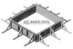
Figure 4
Note: Check the drawings and panel schedule to select the correct panels
- Transport the panels required to the work area.
- Joint the four pieces panels using 2-1/2” nails.
7.3 Lay in of Preassembled Footing Bars.
In order to secure the stub or starter bar at the correct position, a piece or 2 pieces of timber are nailed to the side panel and stub/starter main bar tied to it. Both formwork and reinforcement Worker can perform the work.

Key point
- Bracing should be strong enough to prevent buckling or
- Timber ties/lateral supports across the panel are to be used, especially if the size of Footing is large.
- Panel should be levelled, plumb, square, straight and
7.4 Installation of PVC Spacer.
- Install PVC spacer to maintain required concrete Use approved PVC spacers.
7.5 Pillars / Columns.
- Following the required curing time for footing and form removals, activities to the column may proceed after at least 12 hours.
- Erect the steel bars and splice to the starter bars as per IFC drawing schedule. Should it be required to install supports of the bar to prevent from sway and depletion , a temporary wooden brace or may be an appropriate guy wire should be installed to pillar / column bars.
- Column bar to be spliced shall depend to the type of structure to be constructed.
- Bars for a foundation only and long bar for an elevated structure as illustrated on the following figure.
- Before installation of forms, make sure that the surface of the hardened concrete that will come in contact with the new concrete is thoroughly scraped and cleaned in a manner that shall not leave loosened particles of aggregate or damaged concrete and shall be thoroughly cleaned of foreign matter and laitance.
- Install the four sides of the pillar forms with surfaces applied with approved type of form release agent.
- Check the alignment of end pillar by using Total station surveying tool.
- Clamp or fasten the four sides tightly to ensure that all surfaces are snag fit not to allow Concrete slurry to drip thru joints.
- Provide side support as required to ensure
- Install all necessary embedded materials (if required) such as anchor bolts or insert plates as per IFC drawings. Installation of inserts shall be based on Technip-Issued Standard Construction Drawings for Concrete Works.
- Upon completion, request for Work Inspection Request (WIR).
- Proceed with concrete pouring as prescribed in 2 Concrete Works
- Strip off forms as per guidelines in Table of 6 above.
- Proceed to curing as prescribe in the following
- This The Surveyor will locate and mark all live services that are present in the
Concrete samples poured into cylinder molds during concrete pour on site for crushing tests (compressive strength) after 7, & 28 days performed at 3rd party testing laboratory subject to be witnessed frequently both Client & Contractor.

site (This includes above ground services as well as buried services).
- Any existing service if exposed during previous excavation will be clearly marked, protected, and properly supported during all activities.
- These services (Electric, Telephone, Gas, Oil, Chemical, Water, Drainage, etc) will be clearly marked using stakes and warning tapes. Near these services, special precautions will be undertaken and coordination with the Engineer will be carried out to avoid any damages during the filling and compaction process.
7.6 Installation Process.
The precast unit will be loaded a flatbed after curing until the concrete has reached 75 percent of its 28 day compressive strength but not less than 72 hours from the time of pouring was completed. and protective coating.
- The installation site shall be clean from derbies and any other loose material.
- The location of element shall be marked properly as per drawings.
- By rigging and lifting the element will be installed / erect at designated location.
- The level and align shall be cross checked.
- Pre-cast units dimensions and location of usage shall be as approved drawings.
Program.
- After getting all required inspection, the pouring to be started.
- Re-check for all the arrangements and manpower / equipment’s required.
- The concrete sequence of placing of concrete shall progress from the bottom at every about 300-400mm per layer throughout the foundation.
- Concrete shall not be dropped freely where reinforcing bar may be segregated and not freely dropped from more than Concrete shall be deposited as near as possible in its final position, to avoid segregation due to handling.
- Every layer shall be carefully compacted by using concrete (ACI 309).
- Consolidate placed concrete with mechanical vibrating equipment. Use equipment and procedures for consolidating concrete recommended by ACI309R. Do not use vibrators to transport concrete inside forms. Insert and withdraw vibrators vertically at uniformly spaced locations no farther than the visible effectiveness of the vibrator. Place vibrators to rapidly penetrate placed layer and at least 150 mm into preceding layer. Do not insert vibrators into lower layers of concrete that have begun to
- lose At each insertion, limit duration of vibration to time necessary to.
- consolidate concrete and complete embedment of reinforcement and other embedded items
- without causing mix constituents to serge.
- Temperature of concrete shall be 28 to 32degree (ACI 301).
- One concrete pump and sufficient number of concrete delivery transit mixer trucks are to be deployed for every pouring of the foundation.
- Pump mix concrete slump to be checked for placing of concrete when using concrete pump.
- Sampling, curing and testing shall be performed using the relevant procedures in
- ASTM C 31/C31M, ASTM C 39/C39M, and ASTM C 172.
- Samples for production concrete cylinders shall be taken at the point of placement at the average rate of one per 25 cu. m of concrete placed, with a minimum of one sample taken every day that the mix is used. A sample shall consist of four 150 mm cylinders molded and stored for laboratory-cured test specimens except when field- cured test specimens are required. One cylinder is for testing at 7 days after casting, two for testing at 28 days after casting, and one reserved for later testing if required.
- Chamfered shall be proved to all the edges
- Plastic sheeting or canvas sheeting’ s are to be laid to cover the concrete surface to protect and in case of rain during concreting operation.
- Lighting facilities are to be provided during night pouring of concrete.
- The detail investigation will be done due identify the nature of the concrete defects to advise the suitable material for repairs.
- Manufacturer data sheet will be followed for each company will get approval for the repair material prior to execution of work at site.
- Chipping removal of loses material as manufacturer recommendation.
- 24 hours soaking time is required to prior the application of repair material.
- Third party will be invited to take the samples of concrete repair material.
- Final acceptance will be done by the client.
Transportation.
All precast foundation cast in the precast yard and carried to the site with the help of Boom truck.
8. Night Shift Precaution:-
-
Night Work Permit. (Refer to Internal Work Permit Procedure)
Work activities during the hours of darkness are greatly discouraged due to the associated hazards and will only be allowed by fulfilling requirements under the valid night work permit.
-
Safety Lighting.
Company will provide Safety lighting at the entry point/s of the project as such adequate to the basic security of the site premises or in accordance with the project.
-
TaskLighting.
Tower light or portable light is use in the dark or in reduced visibility, lights will be fitted and used to enable the work area to be adequately illuminated. In addition, amber flashing beacons that give warning of the presence of the vehicle will be fitted and used if necessary.
-
General.
Generally, if otherwise required Company will provide adequate lightingfacility wherever there is a necessity for the lighting for the safety of its employees,material, equipment or any other asset of Company or Client.
9. Environmental Consideration and Sustainability:-
(Refer to client CESMP) To communicate the environmental and social requirements of client to construction contractors for their implementation and compliance.
A. Waste Management.
- Waste shall be controlled and managed at all times.
- Waste shall be transferred by appropriately registered carriers and only removed to licensed sites.
- Wastes shall be kept in a secure manner, suitably contained and labeled.
- Hazardous wastes shall be kept separately and securely labeled containers for the task and disposed of in accordance with the Hazardous Waste Regulations.
B. Waste minimization.
Company shall endeavor to minimize waste streams in line with the principlesof the waste hierarchy.
- Avoidance of waste at source.
- Reduction of waste volumes.
- Re-use of uncontaminated spoil within the works.
- Arrange for recycling of the waste.
- Disposal as a last option.
C. Operations of vehicles and plant.
To ensure minimal impact from the operation of vehicles and plant, operators shall give due regard and implement the following.
- Minimize route and journey mileage to and from and around site.
- Prevent nuisance to the community caused by parking, spoil from vehicle movements, noise and access restrictions.
- Ensure prevention of spillage of spoil, fuels, coolants, hydraulic oils and other vehicle fuels.
- Maintain vehicles.
- Ensure all vehicles and machinery are turned off when not in use.
- Ensure suitable control for the means of access and egress to public highway.
D. Noise and nuisance.
Care shall be taken by the Company Civil Works to ensure good image and relations with the local community by the following.
- The use of offensive language, behavior and or discourtesy to the public prohibited
- Excessive noise from plant, equipment, vehicles and employees being monitored.
- Strict compliance with noise and working hour restrictions.
- Excessive emissions of dust, fumes and odors.
- Tamimi will ensure a high standard of housekeeping and litter control on all sites at all
E. Water Protection.
- Fuels, oils, greases and hydraulic fluids must be stored in bunded compounds a minimum of 50m from the watercourse.
- Excavators will be modified to operate with biodegradable hydraulic oil.
- Diesel to be stored in double skinned tanks/diesel bowsers – refueling of plant to only take place if drip trays are in position.
- Refueling of machinery will be carried out in bunded areas.
- Runoff from machine service and concrete mixing areas must not enter the watercourse;
- Stockpile areas for sands and gravel will be kept to a minimum size, 50m away from the watercourse;
- Runoff from the above will only be routed to the watercourse via suitably designed and sited settlement ponds/filter channels;
- Settlement ponds should be inspected daily and maintained regularly;
- Temporary crossings will be designed to the criteria laid down for permanent works;
- Watercourse banks will be left intact if possible.
- If they have to be disturbed, all practicable measures should be taken to prevent soils from entering the watercourse.
F. Air Quality.
- Minimizing the air emissions.
- All mobile plant to comply with National Mobile Emission Source Standards for Exhaust emissions, particularly black smoke.
- All stationary emission sources to undergo regular maintenance and periodic stack testing to ensure compliance with National Emissions Standards.
- All vehicles, equipment and machinery will be maintained & serviced on a routine basis in accordance with the manufacturer’s specifications and at a frequency agreed with Client. Records of maintenance will be retained.
- Minimizing idling and switch off equipment and vehicles when not in use (e.g. but not limited to: engines, machinery, mechanical equipment, generators, compressors and pumps) when not in use.
- Any black smoke/ unsightly emissions from vehicles and other equipment’s must be reported.
- Care shall be taken by the Company Civil Works to ensure good image and relations with Excessive emission of dust, fumes and odors.
G. Dust Control.
- All material stockpiles to be adequately covered to prevent loss of material through wind erosion as well as dust lift.
- Adequate dust control measures to be implemented when handling friable material (misting, enclosure, etc.).
- All construction temporary access and haul roads shall be stabilized with suitable capping materials (crushed asphalt, gravel, etc.) immediately after grading.
- Contractor to provide an adequate number of water suppression trucks on site required for the regular dampening down of the site road network.
- Water suppression trucks shall have suitably manufactured sprinkler bars installed, which are designed to evenly distribute water on road surfaces.
- Wet the ground before grading and clearing works to prevent excessive generation of dust.
- Use of sealed access roads where possible.
- Traffic speed limited to a maximum of 20km/hr. within active work areas.
- Traffic speed limited to a maximum of 30km/hr. on access roads.
- Where possible, avoid simultaneous instances of side-by-side material handling to prevent excessive generation of nuisance dust.
- Client reserves the right to request machinery is shutdown where standards are not met.
- Emissions of dust from soil stockpiles will be minimized by: minimizing stockpile heights, damping down and covering as needed.
- Stockpiles should be placed in sheltered areas with temporary windscreens erected around stockpiles exposed to wind effects. Handle stockpiled material only when it has been moistened.
- Install dust screens where practical at the site boundary to ensure that dust Emissions do not escape the site.
- All vehicles carrying fill material or soil in or out of site will be fitted with dust sheets.
- Paved roads to be kept clear of soil, dust and debris by installing wheel wash facilities or rumble grids.
- Appropriate and effective dust suppression techniques should be Implemented during earthworks.
- Stockpiles should be placed in sheltered areas where practicable.
- Visible airborne dust plumes are not permitted and will result in suspension of work.