Method Statement for Podium Facade Installation:
1.Purpose:
The purpose of this Method Statement is to define the procedure that will be undertaken by sub Contractor in the Podium façade works in accordance with the requirements specified in the relevant specifications, procedures, and drawings, considering safety and quality of the work activities.
2.Scope of Work:
The scope of this method statement is for the installation of Podium Façade work.
This method statement focus will be the management and supervision of supplied labors.
3.References:
- Approved shop drawings
- Technal installation manual
- Building Envelope General Requirements
4.Responsibility
1.Installation Manager
- the installation manager will be responsible for the day-to-day project activities and supervise the efforts of all other components of the team
- Will manage the sub-contract, site staff, technicians and materials ordering and site installation matters
- Will be responsible for all the correspondence between subcontractors, client, and consultants
- will control/monitor the Installation, design of Shop drawings & erection/fabrication drawings.
- Attend meeting with Façade manager and main consultant on issues concerning Façade
- Will coordinate with QA/QC on quality issues involving façade for the resolution, corrective and preventive action plans
2.Façade Site Supervisor:
- Responsible for the execution of works in accordance with the approved shop drawings and program
- Responsible of the supervision of façade foreman and technicians
- Manages and supervise the labor supply in the execution of works
3.QA/QC Engineer
- will inspect the completed works and arrange the necessary inspection requests
- Ensure materials being delivered to site are in accordance with the approved shop drawings and material submittal
- Liaise with Consultant Inspector during the inspections and coordinate with site supervisors for the rectification of comments and non-conformities
- Ensure that all inspection and testing requirements are carried out as per the project requirements and ITP
6.Procedures:
Installation of the aluminum system, will be done in accordance with the approved shop drawings, ITP and the Technal installation manual
Activity commencement and step by step method:

Add-on Profile and Gaskets Installation:
- Installed Secondary Steel Structure (by others) to be surveyed and scanned to ensure proper steel installation prior Add-on installation.
- Add-on profiles to be safely shifted to installation location as per approved Logistic Plan
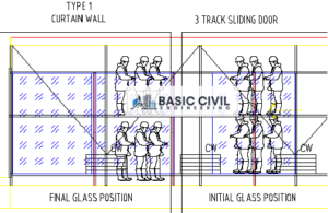
- Scaffoldings to be erected (Figure 1A) as per site safety requirements and to be green tagged prior to use.
- Skilled fitters to be in the scaffolding to procced with installation with full safety precautions.

- Profiles to be placed on steel posts and installed with approved fasteners as per approved SD and TECHNIAL manual.
- Surveyor to check installation of Add-on profiles in parallel with installation
- Inspection to be carried out prior to jump into next step as per approved ITP.
- Once inspection of the addon system is approved, installation of gaskets can proceed. All gaskets connections will be sealed with Butyl Sealant. As per technical recommendation,
Curtain wall add on profile.

7.Glass Installation
- Glass will be delivered in A-frame directly from the factory as below:
- four glass panels to be loaded safety in each certified A-Frame, certificate to be presented to HSE manager
- 1.2 Rubber or equivalent separators to be put in-between each panel and the other to avoid glass scratches and to allow safe lifting later-on site.
- Each glass panel will be rapped by a certified lifting belt and ready to be safely and individually lifted by TC or spider crane.
- Edges of the glass panels to be secured with proper protection to avoid breakages.
- A- Frame height to be higher than widest glass panel and glass to be loaded horizontally in the A frames.
2. Aframes once delivered by M/S BESIX it will be offloaded from the truck using the Tower crane as its hock will be attached to the A frame pull-eyes or direct to lifting belt that safely rapped around the A frame and will be direct shifted to Podium level or nearest point to installation locations.
3. Average glass weight is 300kg with a max weight of 400Kg.
4. Once A frames are secured, Crane boom will be freed and either will be re attached to the individual lifting belt that rapping the glass panel or this will be done by spider crane subject to site conditions.
5. Glass panel to be safely shifted one by one into the mobile RAK (see photo)

6. Mobile RAK to be safely maneuvered near installation location.
7. Certified Electric glass sucker will be hocked to chain block or direct to crane/spider crane hock and then landed on the glass and secured.
8. Once secured glass sucker will be on and glass will be safely removed from RAK to the two pivoted wooden block
9. Glass will be flipped (or not) using the glass sucker to get the external face of the glass attached to the glass sucker.
10. Once glass sucker is secured, team leader should attach it to approved chain block OR approved spider crane hock (based on site conditions) or lifting anchor point.
11. Glass to be slowly lifted and guided by installation team leader, see figure
12. Glass will be orientated, so the glass logo will always be at the bottom right.
13. Glass panel to be secured on the add-on profiles by toggles, as per the approved shop drawings and Technal Manual
8. Weather Sealant application:
- Weather sealant Dow Corning 791 are stored in a chemical temperature-controlled room.
- Before application of the weather sealant, backer rod is installed in the between the glass
- Glass edges are cleaned with Isopropyl alcohol as per Dow Corning recommendation
- Glass edges are taped with masking tape
- Weather sealant is applied
- Weather sealant is tooled using a proper tooling tool, soapy water may be used to have a smooth sealant finish
- Tape is removed
- Wherever the sealant is accessible, signage is installed to warn about the fresh sealant being applied
9. Stick ACP cladding installation:
- A support in GI sheet is installed on the Secondary Steel Structure that will receive the internal ACP cladding
- The ACP is then installed in the following sequence:
- Bottom transoms
- Top transoms
- Vertical mullions
- Intermediate transoms

10. Firestop installation:
- Horizontal Firestop system (SIDERISE) is the same being used in the tower, with the same detail.
- Refer to method statement for its installation
11. Logistic (Material, Equipment and Plant:
- Material loading and temporary storage shall be in accordance with traffic management plan
- Materials will be off loaded on temporary storage area and transferred to the required location for installation using tower cranes and loading platform or manually by access hoist/lift.
- Methodology for the installation of scaffolding will be submitted separately by specialist contractor.
12. Plant and Equipment:
- Spider Crane
- Tower Scaffolding (skyscrapers scope limited to 4M Hight scaffolding)
- Loading Bay (if needed)
- Tower cranes
- Vacuum Glass lifter
- Power stacker lift or jack lift
- Chain Block
- Winch Machine
- A-frames
- Survey equipment
- Torque wrench
- Electrical hand tools
13. Supervision Arrangements:
The supervision arrangement for these works is explained by Figure 6. At the front line there will be the scaffolders, safety, survey staff and the construction operatives including hired labor supplies (helpers, scaffolders, supervisors) all involved in preparation and execution of works and for the purposes of this method statement they will be referred to as tier 4 staff. Their managers who involve SKC installation manager and Staff will be tasked with managing and overseeing their work. The Installation manager will have direct links to the managing staff. The Construction Manager will then co- ordinate with the installation manager regarding the works required for the construction of the works.
- All operators/riggers/watchers will be undergo approved third party and briefed with TBTs.
- For MEWP, all operators must be certified by IPAF (to be arranged by BSIX on SKY cost)
13.1 Human Resources:
- The Projects Manager shall review and approve the methodology for the execution of the works, and ensure that the works are implemented in an efficient manner. The Project Manager is generally responsible for the overall project execution, quality, and safety.
- The Installation Manager shall be responsible for the implementation of methodstatement and ensures that all involved site construction personnel are aware of this method statement and shop drawings are followed. He shall ensure that the execution of works shall be carried out in safe manner. He will also be responsible for the monitoring of the work progress on daily basis to ensure activities are accomplished as per the construction program.
- The Site Supervisor shall ensure that the works are carried out according to the design, approved shop drawings and procedures. He will be responsible on behalf of the Contractor to coordinate, check and follow up the work with relevant parties and ensure that proper sequence of activities are followed in order to achieve target completion. He will ensure that safe work practices are followed for all works under his care.
- The QA/QC Engineer shall ensure that works are carried out in accordance with the Quality Plan. He shall ensure that materials being used are in accordance with project specifications and approved by the Engineer.
- The Surveyor shall be responsible for setting-out the location, line and levels, plus other dimensional requirements in accordance with the design drawings and approved shop drawings. The Safety Engineer will monitor and implement all HSE related issues. He shall ensure that all necessary requirements regarding health, safety and environment concerns, risk assessment are met and adhered to.
- The Safety Engineer shall ensure that all permits and authorization are on hand prior to starting any site operation (if required).
- The Foreman will be responsible to carry out the work in safe manner and to supervise the work force together with the proper execution and monitoring of works, and all appropriate checks will be carried out during each stage of the works.
14. Health & Safety Requirements:
The Project Safety Plan sets out the general safety policies and procedures pertaining to all the contractor’s construction activities. This task specific document identifies and further refines the applicable safety measures and procedures that will be implemented to ensure that the works to prepare and construct the stair landing slabs are conducted in accordance with the Project Safety Plan. Please refer to attached HSE Risk Assessment for details.
- Tradesmen and helpers should wear suitable PPE.
- Personnel working on heights will be required to wear safety harness.
- Necessary guard rails and toe boards will be erected as directed
- Safety lights shall be provided
- The area shall be properly barricaded.
- All power tools to be inspected and certified by BSX safety officer.
- Safety works permit to be secured.
- Work in charge to conduct a toolbox meeting and communicate the Risk Assessment to the workers before the commencement of the activity.
- If ladders are to be secured at the top and bottom and must be positioned at a safe angle of 75 degrees with respect to horizontal axis.
- The workers above 1.6 meters height should use full body harness and anchor it to a rigid surface that should withstand 12KN for one person.
- Work in charge should check all the lifting devices before lifting and ensure that there are no loose materials on the load. The load must be stacked properly. Foreman should check the working area at start and end of activity on daily basis.
- Scaffolding foreman shall provide a safe working platform for the personnel’s working on heights (by BESIX)
- Site engineers and foreman must ensure that the work is being carried out in a safely manner
- All works shall be performed in accordance with the local authority regulations, project HSE standards, Employer’s HSE Manual and Contractor’s HSE Plan and Procedures.
- Supervisor will ensure that Mandatory Personal Protective Equipment is always worn by site personnel during the designated tasks.
- Prior to commencement of any activity, all operatives will be given in a general site safety induction by HSE Personnel, the Site Engineer/ Supervisors will also conduct TB talks and method statement briefings to the personnel involved in operation. Permit issuance of specific tasks should be done if required.
- All worker at the slab edge must wear safety harness hooked on appropriate hooking point. And all tools must be attached to a lanyard.
- Coordination and exclusion area must be in place when the façade activity start. Exclusion area for the area below the façade installation.
15.Environmental and Sustainability Requirements
- All waste materials will be segregated and will be removed from the site. Waste materials will be transported and dumped at approved dumping areas provided by Brookfield Multiplex.
- Disposal will be carried out as per the local legislation and practices in force and in line with Brookfield Multiplex Construction Environmental Management Plan, Waste Management Plan, LEED Management Plan.
- All equipment will be maintained in accordance with the manufacturer’s instruction for low noise operation.
16. Hazardous Substance Management
- No hazardous substance associated with the work.
17. Security Arrangements:
- Site supervisor/Engineer will notify the security regarding the number of personnel who will be working at site. He will coordinate with the main contractor for all the requirements that need to be submitted prior to commencement of work.
- Gate pass will be obtained for the Incoming and outgoing materials and the process will be in accordance with site procedures.
18. Document Records:
- Permit to works
- Toolbox talk
- WIR- Work inspection requests
- Clearances (if required)