Contour Mapping – Characteristics, Methods & Uses.
Contours are the lines that connect points on the earth’s surface at the same height. A contour is a line that cuts through the ground and meets a level surface made by joining points at the same size.
Contour Map.
The map with the contour lines is called a “contour map.”
The contour map shows how high the land features are and where they are about each other on the plan. It serves both the plan and the section.
Contouring.
The process of tracing lines on surface of earth is called contouring.
Contour Interval.
Contouring is the process of drawing lines on surface of the earth.
Horizontal Equivalent.
The horizontal equivalent is the distance between two next-to-each-other contours on the horizontal plane.
The distance between each set of contours is the same or stays the same, but the equivalent horizontal changes depending on how the earth’s surface slopes.
Contour Gradient.
Contour gradient is the name for a line on the ground that stays at the same angle as the horizontal. A tool called a Clinometer is used to measure it.
Related Posts
-
What’s the Contour Mapping?
-
Responsibilities of a Land Surveyor
-
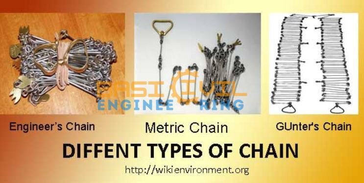
Five Different Types of The Chains In the Civil Engineering
Characteristics of Contour.
- Contour lines always make closed loops, but they can close either on the map or outside.
- Contours are always on the opposite side of the steepest slope.
- Along the contour line, all of the points have the same height.The horizontal equivalent for a given contour interval is based on the map’s size and the land’s shape. The flat match goes down as the slope gets steeper and steeper.
- If the contours are parallel and distance between them on map is always same, then the slope of the contour is the same.
- The plane surface is made up of contour lines that are straight, parallel, and evenly spaced.
- The uneven contours show that the land is rough.
- For depressions, the value of the contour line goes down from the outside to the middle.

- In hill contour mapping, the contour value goes up from the outside to the middle.

- The Contour lines go straight across the ridge. If the higher values are inside the curve or loop, this shows the ridge.

- The contour lines go straight through the valley. If the higher values are outside the bend, it shows the valley.

- Two lines with different heights don’t meet or cross each other. But the contours seem to cross each other in the case of a cliff that hangs over or a cave that goes into a hill.

Methods of The Contouring
There are mainly Two methods of the locating contours.
1. Direct Method of the Contouring.
2. Indirect Method of the Contouring.
1. Direct Method of the Contouring.
In this method, the contour to be drawn is actually traced on the ground by finding the points of that elevation. After that, the horizontal position of the points is figured out and marked on the plan. So that you can’t mix up one set of pegs with another, each set is given a different color code.

- Since the points are found directly, this method is more accurate than the indirect methods and is usually used for small areas.
- The main problem with this method is that needs to be faster and easier to using. It also needs to be better for the contouring larges areas.
2. Indirect Method of the Contouring.
In this method, the points located and surveyed are not necessarily on the contour lines, but the spot levels are taken at some selected points called guide points & the levels of points are determined. The horizontal positions of these points are then found, and the points are plotted on the plan. Then, their locations are marked on the plan, and the contours are drawn by interpolation.
This way of sculpting the surface is called “contouring by spot levels.” The indirect method is more accessible and works better for large areas than the direct method.
The indirect method of contouring is mainly made up of three ways.
i) – Grid Method or Square Method.
This method measures small to medium areas and land with fewer hills and valleys.
- The area to be surveyed is divided into a certain number of squares. The size of the courts depends on the type of ground and the contour interval. Most of the time, it ranges from 5–30 m.
- Interpolation finds the points on the different contours based on the heights of the grid points.
ii) – Cross Section Method.
This method is best for taking measurements along a long, narrow strip, like a road, railroad, canal, etc.
The Cross sections are on the ground at right angles to the route’s fixed line or center line. The cross-section lines don’t have to go through the center of the work at right angles. This can be tilted to the cross section’s center lines at any angle.
How far apart the cross sections depend on how the ground is and how far apart the contours are.
The average value is between 20 and 30 m in hilly areas and 100 m in flat areas.
On the plan, the heights of the points along the section lines are drawn, and then contours are made as usual.
iii) – Radial Lines Method.
This method works best for small hilly areas where radial lines can be drawn from the highest point to cover the whole area.
- The Grid points are taken on the radial lines, and their heights are found.
- Through interpolation, the contour lines are made.
iv) – Controlling Point Method.
Here, the heights of a few selected key or controlling points are found. Interpolation is then used to draw the contour lines.
- This is an approximation, but it’s quick.
- This method works very well for sloping ground that is pretty even.
Uses of the Contour Maps.
Contour surveys are done at the start of any engineering project, like a road, railway, canal, dam, building, etc., so contour maps can be used for many things. Some of the primary uses are listed below.
- To figure out what kind of land it is.
- They are used to find the best or most cost-effective site.
- To figure out where the canal should go so that it goes along a ridge line.
- To mark the paths of the roads and railways so that as little earthwork as possible needs to be done.
- They are used to figure out the catchment area and the amount of water.
- To figure out the particular route’s given grade.